For the previous entry in this series, click here.
What Works?
Digging in, there were some good signs. Once home, the unit powered up immediately and without the flickering/stuttering bug. All of the panel lights appear to work, and it ran it’s startup calibration of the optics without interruption. It required some minor fiddling with the paper cassette, mainly because the connector does not have positive engagement and I failed to fully connect it the first time. With all of that settled, the “Jam” icon disappeared, and the “Copy” button turned from orange to green.
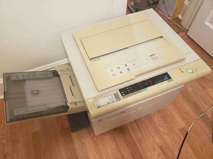
Figure 1: The copier, operational.
I ran off a few quick copies of my scratch paper, and they were remarkably good. The lines were black, the grays varied where my pens had bled or been splattered. It all has that classic “copied frantically, minutes before first period” look that I remember so well from middle school.
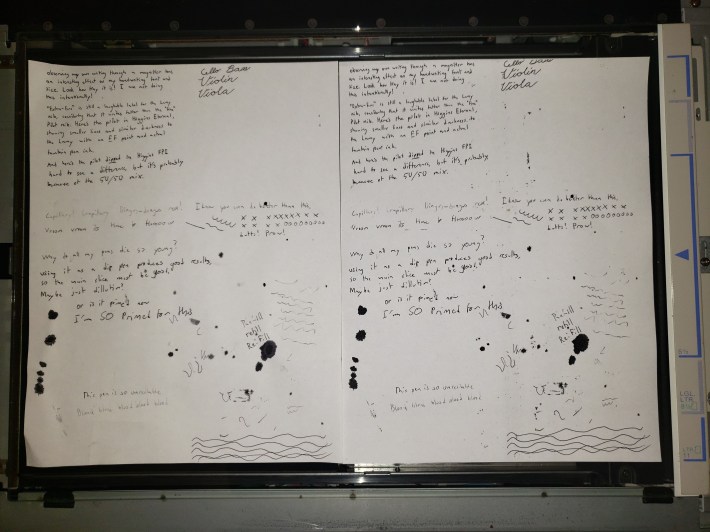
Figure 2: The original test sheet (left) and the copy (right)
Of note was a distinct streak of dustiness down the middle-right portion of the page. I guessed this had something to do with a dirty roller. I also spotted a fair deal of flattened, baked-on chunks of… oil? wax? Most likely, some old, dry lubricant had shaken loose in the move and falling into the paper path. I was extremely impressed, regardless, by the straightness and tight margins of the facsimile. I got excited, and ran a few more copies of random sheets lying around, to basically the same result. I will provide color scans at some point, showing the gray levels and the grease spots, so you can judge for yourself. I was mesmerized by the simple device’s ability to reproduce gray through random dappling, purely by the nature of its design and with no help from digital imaging.
So far, we have three obvious, distinct problems visible:
- Black smearing on the right-middle quarter of the sheet
- Grease spots on the pages
- Intermittent power issues (I confirmed these after a break, they occur any time the unit is left unplugged)
A Look Inside
Nothing further could be deduced from the outside, so it was time to dive in. Minolta has provided us an easy and obvious way to do so. Here’s a look inside the front hood:
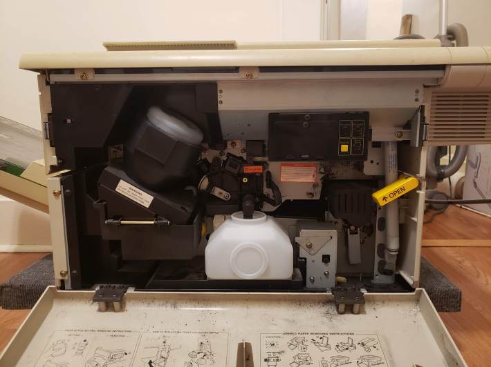
Figure 3: The maintenance compartment.
Practically everything an end user could need is accessible here. The toner bottle and feed are on the top left. They are removed by lightly twisting the entire assembly clockwise and pulling out. At the bottom, front and center, is the toner disposal bottle, which captures chunks of toner not fit to be applied to the drum. You can remove this a lot of ways, but generally it’s easiest to do with the mechanism fully open (see next section). Along the right side is a gas strut responsible for holding the printing mechanism open, and a large handle labeled “OPEN” which releases the mech. In my unit, both struts (there’s a mirror one in the back) had come off their tracks, and were banging around on the floor. Make sure you check their engagement before trusting them – mine are not strong enough to support the weight of the upper module anymore.
At the top right there is a small plastic box with a reset button (important), a “power saving” switch, and a “dehumidifier” switch, plus a pinhole button labeled “Serviceman Only”. The power saving mode allows the unit to switch its heater off when idle for more than some fixed period. The reset button is critical, since it must be pressed after a jam is cleared and before the front door is closed in order for the machine to register that the jam has been cleared.
Going Deeper
Opening the mechanism, and re-attaching the struts only made things more complicated. From here, I could see the complicated system of conveyors and rollers, the photosensitive drum, and the “developer” or heating element.
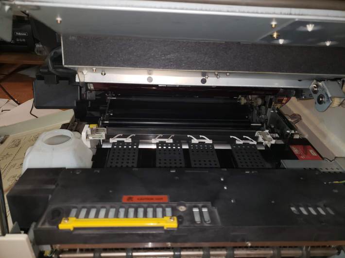
Figure 4: The interior mechanism, cleaned. Visible from bottom to top, are the drum (brown) the rollers (black) the cleaning blade (silver, white) the conveyor belts (gray) and the developer (large chunk at bottom)
At this point, I stepped back, and decided to plan ahead and prioritize the power failure. As interesting as the innards were, they were less pressing and the solution was more obvious. The rollers and blades were caked in decades of melted, wet toner, and fixing that would take time and isopropanol.
Undressing
Rather than start scrubbing, I set the lid back down and went about hunting for screws. The document cover came off without any tools, but the plastic frame around the glass proved difficult. I needed to remove the entire right body panel in order to access the clamping screws holding the control panel on, and then slide the control panel away for the frame to come free. On top of that, each of the top frame’s screws are covered by a small snap-in piece that must be removed with extreme care, as 30-year-old snap fits aren’t known for their toughness. With the top off, the rest of the panels fell with relative ease. I did not remove the left panels (feed side) because there wasn’t anything interesting over there.
Removing the glass was an additional challenge. There was likely a specialty tool used to undo the access panel at the aligning edge of the glass, but it ended up coming up with the frame anyway. Under that is a large retaining/aligning bar. Removing the left and right screws of that released the platen glass, which came free with some careful prying, having adhered somewhat to the rubber pads.
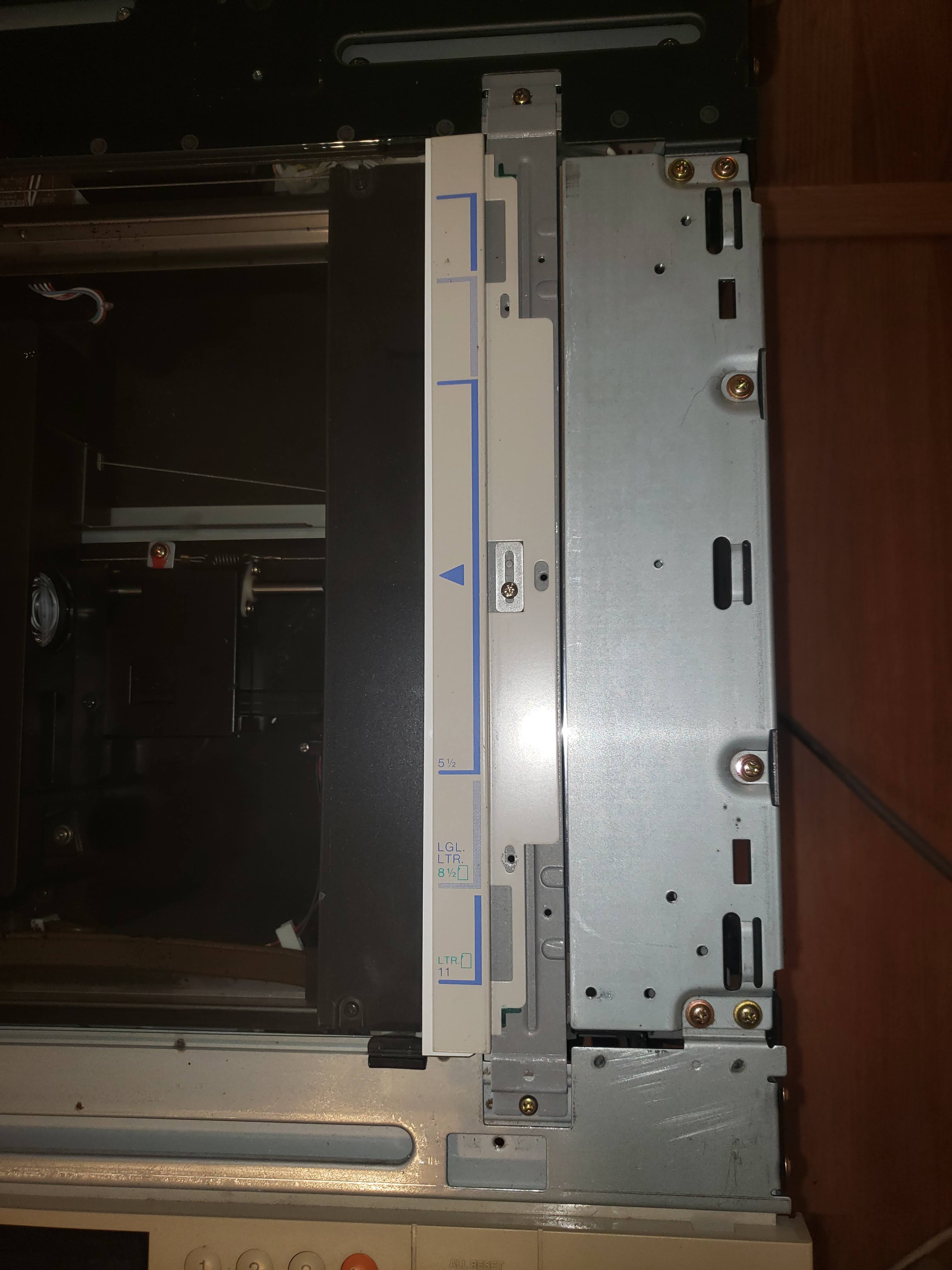
Figure 5: The retaining/aligning bar.
The copier is a computer wonder inside. It reminds me of a Commodore board, something designed pre-microcontroller that needed to have many sensors, servos and relays attached to a central brain. Almost all of the circuitry and wiring is in the back.
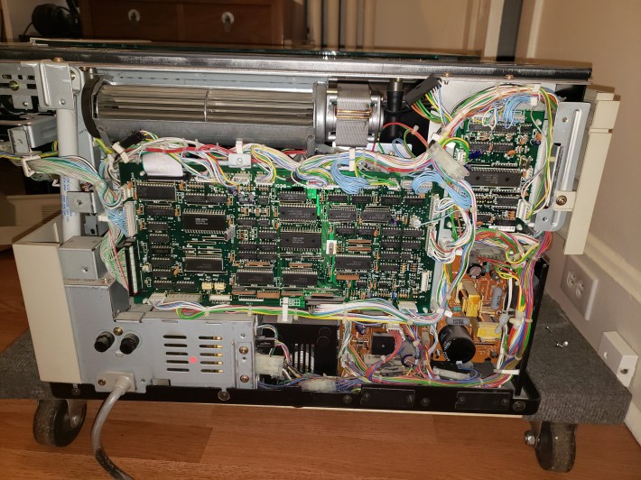
Figure 6: The controller compartment revealed. The largest board is the main controller, and there are two separate brown power PCBs at the bottom right. The mains part of the power supply is encased at the bottom left.
I was awed by the availability of everything. The wiring is a rat’s nest, sure, but the single-sided PCBAs and large, discrete components mean this should be easy to work on, should one of the elements burn out. Following Berny’s advice, I poked around the power boards for a 2-pin connector near a trimpot. True to his words, there was but a single two-pin plug, and a single potentiometer. Not quite right were the labels, but I can forgive The Copier Doc. The instructions were clear!

Figure 7.1: Rough location of the power board.

Figure 7.2: Closeup of the power board, showing connector PJ3 “Cutoff” (top right of board, with a single blue wire)

Figure 7.3: The upper right corner of the power board, showing the trimpot (white with yellow marking)
Interestingly, PJ3 is also labeled “cutoff”, which suggests to me that it’s used in monitoring voltage availability in order to cut the supply if it gets too low for the digital hardware. Tweaking the cutoff sounds like patching a symptom (low voltage) rather than solving the problem, so I’ll take this all under advisement. Due to my multimeter being a little… demolished at the moment, I left this for another time. I might end up removing this board and replacing the electrolytic capacitors. 30 years of relative dormancy is not good for these things, though they don’t show any sign of overheating or offgassing. There are eight unique caps on the board, from a 4700 uF input(?) to a tiny nanofarad-range ceramic (I wouldn’t replace this). Since these are the only wear-prone components that I’m aware of, except for some healthy-looking power transistors, I bet changing them out would do wonders for the copier’s health. Unfortunately, I don’t have a ready supply of fresh capacitors lying around, so this would have to wait.
The Three “C”s
Backing off from the power stuff, I thought it would be best if I tried to correct print quality. The solution appeared trivial: scrub the muck off of the parts that touch the paper, and the paper won’t have muck on it. Be very careful here! A number of edges are razor sharp. I got numerous, deep cuts and didn’t even notice until I saw blood!
That was basically it.
The blade that lies just before the last pinch roller was so filthy that I used probably 10 paper towels just scrubbing back and forth until I could see the metal again. I had to use the yellow knob (on the maintenance door side) in order to run the pinch rollers through a few cycles as I scrubbed. That was tedious, since they tended to pick up scraps from the aforementioned blade and press them into sticky discs. I’d recommend cleaning the blade completely first.
The drum was scary, since it’s an optical surface, but then I realized that it’s meant to withstand the abrasion of a hundred-thousand sheets of copy paper. There were a few smears on it, which came off with very light pressure and alcohol. In order to clean completely around the drum, I had to close the machine, run an 8.5″ x 11″ copy of nothing (all black) and then shut it off again. Since the drum isn’t exactly one sheet around, this offset it some unknown amount each time. After scrubbing, the recently-cleaned region would print some murky, dirty-window looking smears in the black regions, but that clears up after a few copies. I found it was helpful to have a shearing light on the opposite side of the drum from me, so I could see where the matte gunk was.
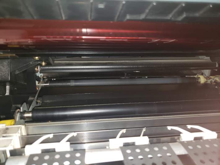
Figure 8: A closer view of the clean elements. The drum is the red/brown thing up top.
At this point, I believed I’d cleaned everything inside, but it was still printing lighter bands on the outer edges of the paper. It turns out that those are an artifact of printing full-black sheets, probably because of a slightly uneven charge in the drum, or uneven deposition of the toner when it’s in high demand.
I scrubbed the rest of the interior, including all of the horizontal surfaces that had collected a film of powdered toner. I did the same in the platen housing. The glass came clean with no trouble, but I was a bit nervous sweeping stuff up around the lens and mirror. I have no idea how toner got in there. I cleaned the illuminator’s rails in the process, which may have been a mistake. They are lubricated, and the scanning action started screeching after this.
In part 3, I’ll go over reassembly and functionality, including lubrication, because a 30-year-old machine with 30-year-old lubricant technology should not be expected to move smoothly.
Part 3 is now available! Check it out here.

Pingback: The Minolta EP-410Z: Part 1, Intro | Profanity Filter Testing Domain
Pingback: The Minolta EP-410Z: Part 3, Release The Pixies | Profanity Filter Testing Domain