This is part 3 in a series. For the previous entry, Go To Part 2. Or, check out Part 1.
Out of the frying pan…
… and into a slightly cooler frying pan! Good news, things are getting better! Here are the critical issues to address, now that the copier is clean and technically serviceable:
- The horrible screech when the scan head returns
- The weird, transient power issue that only happens after being unplugged for a while
- Frequent misdiagnosis of jams
- A new, more frustrating power issue where the machine shuts off under load
What was that last thing?
Yes, there is a new issue that has cropped up since using and testing the machine for a week or so. As number 4 says above, the machine fails after being plugged in for too long as well as being unplugged for too long. The issue is much the same in either case: The startup current needed to get something moving (like the main PSU, or the high-voltage system, or the illuminator) is too high, so the system resets. Thankfully, these are power-side and not digital-side, so they should, in theory, be obvious. Theoretically, the solution to issues 2 and 4 will be the same thing.
Easy stuff first
The screech was a simple fix. I could see the wear marks on the scan head’s rails. I assumed these were where metal rode on metal, but it turns out there are plastic boots on all of the sliding elements.
Putting chemical compatibility over pure lubricity, I chose a dry teflon/PTFE lube that I also use for my bike chain. It dispenses as a thin fluid, and eventually turns into something like a graphite powder… but more plasticy. It poses a very low risk of melting/swelling/cracking plastic parts.
This fixed the screech immediately. Scratch issue #1.
Back to the Caps
Again, we’ve set aside Mr. Buta’s advice for the sake of engineering correctness. A drift in power supply settings is a symptom, not a root cause. Since we know that inductors can’t really go bad, and resistors tend to fail obviously and catastrophically, the obvious culprit should be capacitors – namely electrolytic ones. Thankfully, as I mentioned in part 2, there are only 8 capacitors on the voltage regulator board which monitors that PSU voltage, and only 6 of them are electrolytic.
Unthankfully, I retrieved my Harbor Freight multimeter from the garage to discover that the battery was dead, and it had taken the rest of the unit with it. Imagine my despair when I realized that a bare-bones replacement would be $25 and shipping, then imagine my maniacal laughter as I devised a plan to forego the meter entirely!
First, I removed the rightmost power board, which required far more screws and connectors than I would have expected. Then, I pried off the main heatsink from the two big power transistors/regulators. The larger of the two, labeled STK7563LM, connects directly to the trimpot at terminal 4: “V1 SENSE 2”. This power board is remote-sensing, and it appears to provide the 5V and 24V power for the computer and motors, respectively. Since it’s V1, this is specifically something to do with the 5V supply, thus the 5.2V nominal The Copier Doc suggests.
This is Not Good™. This is the low voltage power supply board, but our problems happen when the high voltage, high power stuff is engaged. That means the power shortage is happening closer to the AC supply. Even if we tweak the power to the brains, there must still be a reason it isn’t enough to go around.
First thing’s first – check the caps. But without a meter, how?
Fool! This is why we steal $14,000 mixed-signal oscilloscopes from work – for the times when our $5 multimeter gives out!
Yes, that’s right. I removed each capacitor from the board (in order of decreasing size), soldered them into a naive RC charging circuit, and manually flicked on the desktop power supply while recording the voltage. For a 10V supply, with a 100 Ohm resistor in series with a capacitor of unknown capacitance, the capacitance could be found as
C = T / 100
Where T is the time it takes for the voltage across the capacitor to reach 6.32V, or one time constant’s worth of charge. On my fourth try, I found that 1000uF capacitor C5 had only 2/3 of its rated capacitance. Repeat tests verified this with little noise.
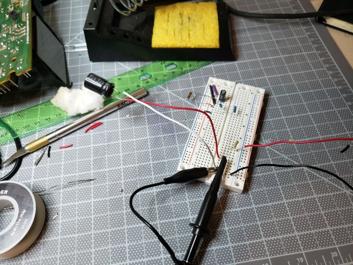
Figure 1: The very silly test circuit with the bad cap mounted
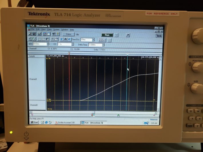
Figure 2: The MSO showing a Tau of 69.69 (nice) ms, which calculates to 696uF
Luckily, I had a similarly-rated salvage capacitor in my Magic Box, which tested correctly at around 1000uF (but rated only 85°), so in it went. I decided to leave the last two, much smaller caps alone for now, since I don’t have a reasonable way to mount them for testing.
I plugged this board back into the copier to find that… basically nothing had changed. It started up quickly and with no issues after being unplugged for a time, yes, but it immediately resumed conking out at the first copy. Granted, it worked fine after some restarts, but that has always been the case. Clearly, there’s something else wrong here.
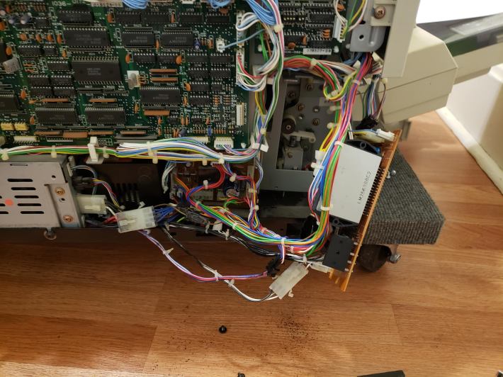
Figure 3: The board,plugged in for testing.
Thinking…
The following section is largely contemporaneous notes I took as I attempted to hunt down the problem with little skill. I didn’t want to forget what I’d tried. You can ignore pretty much all of it if you’re here for entertainment.
This round of tests presented further confounding issues. While the printer appeared to be working better the first time it was powered on, it resumed the rapid on/off ticking after being unplugged for ten seconds. Plus, it sensed a number of new jams which may or may not have been the fault of a worn intake roller. After all this, I still haven’t checked the nominal voltage across PJ3.
I wondered if the voltage regulator itself experiences wear. I’m not quick to blame solid state components, but it could just be a setting.
PJ3 represents the voltage between CUTOFF (floating) and V1.
I tested PJ3. Quite dangerously, the left pin (V1), which has no wire, discharges rapidly and causes the switching regulator to lose its damn mind when touched by a probe ground. Clearly, this is not what the instructions meant. I tested the voltage from V1 to ground, and found it was only 3.9V. I’ll have to put some acetone on the pot to move it, since it has been painted in place. The right pin is CUTOFF, which is apparently a failsafe that turns the whole STK unit off when grounded. The single wire is connected to a safety circuit on the brainboard, which has a low-impedance ground that it can dump that power into to shut the system off in an emergency.
For all intents and purposes, this board IS the reference design #1 proposed by STK, down to the capacitor numbering. Pins 4 and 5 sense voltage drop across RS1(a) and adjust output voltage accordingly. V1 should not be 3.9V, so the reference needs to be adjusted. The reference design specs a 0.22 Ohm resistor in this place, while the board has a 0.1 in this location (RS1a). There is not supposed to be any resistor between RS1 and pin 4, and yet we have a 500 Ohm trimpot…
I checked the resistance of VR1 out of circuit with a voltage divider. As implemented (as a rheostat) R = 2.2 Ohms. The max R of the pot is 620 Ohms, so this is pretty baffling. Why spec a 600 Ohm VR for what is normally a jumper?
I found a newer version of the datasheet, which is digital and includes Rev F of the device. This document is essentially identical (but more complete), except page 1 explicitly says:
High-precision setting of output voltage, eliminating the
need to use a variable resistor for adjustment.
L1 and L2 are identical units inline with their respective sensing circuits, with L1 in series with RS1 and L3. While I can’t guarantee the poorly-labeled, real life components are 200 and 10 uH precisely, this is likely not important. The inductors are just big inertial masses and these ones are clearly very big. I mapped out the relevant components on the real PCB, shown below.
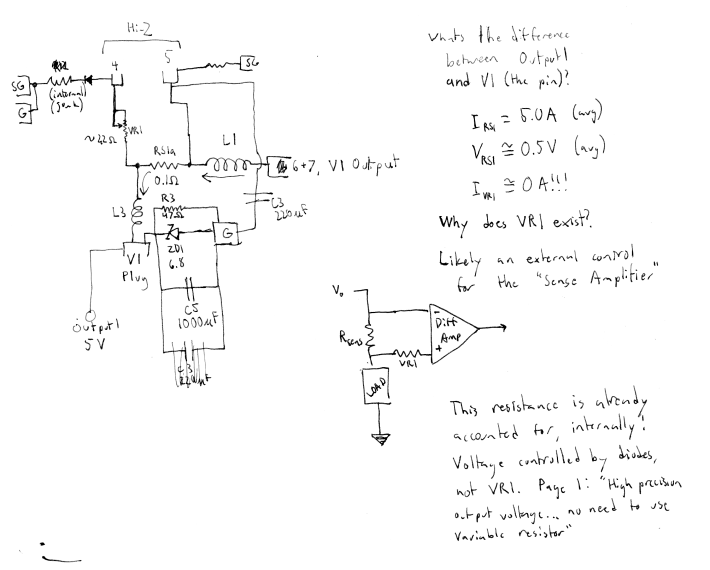
Figure 4: A rough map of the 5V regulator circuit. Note that current should not flow through VR1.
VR1 sits in front of a high-impedance sensing output. No current should flow through it and thus no voltage should be induced. So why does VR1 exist!?!?! In the reference PCB, it’s a wire. Not even a jumper. The document explicitly says it’s not needed, and the internal diagram suggests that the 5V level is maintained by semiconductors. The only reason we’d want a trimpot here is to trick the device into producing less than 5V, which makes very little sense.
My crackpot theory, at this point, was that VR1 was meant to be some kind of factory testing device that could simulate a low voltage condition. It’s resistance would be turned up until V1 dropped too low, and the system passed if the auto-shutoff engaged. This would also explain why it was set to its minimum value and glued in place. Most likely, the minimum position was 0 Ohms when the unit was new, but contamination and aging gradually turned that into a nonzero value.
To test this theory, I replaced VR1 with a fixed, but smaller resistor. It was easy enough to solder in a 1.5 Ohm baby resistor. Lo and behold, with this modification, V1 rose to 4.60V. If we assume we’re working roughly in proportional (and not additive) settings, we take the percent change in resistance…
(1.5-2.2)/2.2 = -31%
and the percent change in voltage…
(4.6-3.9)/3.9 = +18%
Then our correlation (boldly assuming linearity) is -31:18, or about -1.7:1
That is, if we want a 1% change in voltage, we need a -1.7% change in resistance.
(5.2-4.6)/4.6 = 0.130
0.130 * -1.7 = (R – 1.5)/1.5
R = 1.17
Again, linearity is probably not a good assumption, especially for extrapolating here, but it does seem that the last 0.8V need to be dialed in pretty carefully.
A few checks later and… still nothing. V1out maxed out at around 4.8 V, even with a 0 Ohm resistor in place of the trimpot while V2out holds steady at 24.0. Clearly, there is something wrong in the 5 volt system. Let’s explore.
The supply voltage is good, a steady 36V from the rectifier. What else lies in the power/regulation path for the 5 volt regulator? Some filtering capacitors, whose capacitance shouldn’t matter as long as they’re not shorted, but we’d know if they were.
A 47 Ohm resistor, R3, pulls up V1 from GND. I noticed some tiny scorch marks around one leg and found its in-situ resistance to be 23 Ohms. It might just be other elements passing current, but I figured it was worth resoldering at least. Upon removal, it appears my 50-year-old ohmmeter has some issues with this particular range. I replaced it with a similarly-sized power resistor anyway.
Blame the tools.
After all this, I started to wonder what the sensing signals looked like. A chopper regulator should have some really obvious PWM going on, but when I probed pins 4 and 5, they showed a steady, high voltage.
It turns out I shouldn’t have been relying on my oscilloscope for DC/RMS readings. It doesn’t do that. In fact, it appears to be essentially the same as the -PEAK measurement, which, at 4.8V is less than the Peak-Peak distance from 5.2V. This became apparent when I zoomed in, and found that my steady-state signal actually had just enough noise to confuse the elderly, non-storage Tektronix scope. It turns out that the unit idles just fine at 5.2 volts. It does spike when the scanner is operating, as high as 5.5, though again, I believe this is just noise. I trust my eyes enough to see that the general trend is around 5.0 volts.
I was now curious to see if putting a 1.5 or 2.2 Ohm resistor back in for VR1 changed this level meaningfully. I should have noticed Berny’s other note:
EP-410/470
POWER UNIT
Flashing keyboard or other int. electrical symptom. These machines use a Voltage Regulator IC in the P.U. which is known to blow. Replace with STK 7563F, available anywhere.
Which concerns me, since this machine uses the 7563LM, a higher-amperage version of the F. Deciding not to push it, I opted to put some resistance back in the slot.
With a 1.5 Ohm generic soldered into the VR1 position (I should just change it to a pair of friction-loc ports at this point) I set the machine to rest for the night. Its last reading was about 4.9 V at startup, which is technically within spec. I wouldn’t be able to know if the main power issue (inability to start up) would persist without letting it sit overnight.
Mysterious Brown Stains
Before going to bed, having done all I could do with the power supply, I noticed that the last couple of copies had still come out with greasy, brown stains mashed into them. This, coupled with frequent jamming at the feed unit, made me suspicious, so I tore into the cassette. This wasn’t the first time the feeder had had issues, since it was partially unscrewed when I received it.
It turns out that, like many 80s electronics before it, a portion of the rubber inside had decayed into a dry, crumbly wax. The separator pad, a piece of high-friction material against which the pickup roller fans and separates the sheets, had decayed into a crusty, dry wax. It looked a bit like soap that had been wetted and then left out in the sun.
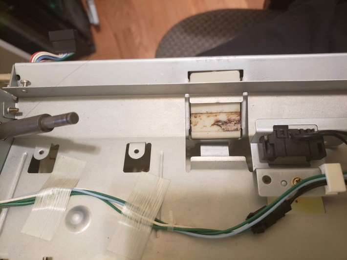
Figure 5: The separator pad with 75% of the wax removed.
There wasn’t anything I could do with that, so I scraped it out and wiped the region down with alcohol. But this presented a new problem: with nothing in the pad’s place, sheets just ran up against the edge of its slot and jammed. I considered asking my grandfather for some of his old sculpting wax, which had a remarkably similar texture, but settled on taping over the space with electrical tape as a stopgap. Some techs on Copytechnet.com had mentioned this when discussing the horror of Minolta feed trays, though they suggested silicone self-amalgamating tape.
Unsurprisingly, removing the wad of disgusting, slimy wax from the feed unit removed the brown, waxy stains on paper entering the copier. I will likely need to scrub the insides again in order to completely remove the lasting effects, namely, the streaks on the drum that have appeared.
Next Up
The remaining work appears to be cleanup. As long as I don’t encounter the startup issues after 12 hours, I’ll feel safe to re-close the unit and do a final swabbing with alcohol. There are a few more toner-soaked gears that are now accessible, which are also in need of a good cleaning and re-greasing. Let’s go over the To-Do list:
- Clean the wax off the paper path, esp the drum
- Clean inside the feed jam sensor, which gets stuck regularly
- Clean and lubricate the main drive gears in the electronics bay
- Find a suitable replacement for the separator pad
- Possibly put the original 47 Ohm power resistor back in R3
- Re-assemble
I pray that I haven’t forgotten where the screws go.

Pingback: The Minolta EP-410z: Part 2, Digging In | Profanity Filter Testing Domain
So, how did it end? I’m also fiddling with a 410z and loved your journal. Thanks for the pics and the effort of documenting it!